NOTE: The video card should be removed from the chassis in order to install this
cooling device.
CAUTION: Removal of the original heat sink my void your manufac-
turer’s hardware warranty. Please consult the manufacturer if unsure,
and keep all original parts in case of a return/RMA. Installation of water
cooling products is done at the user’s own risk.
!
VID-398GX2 Installation Guide v 1.0
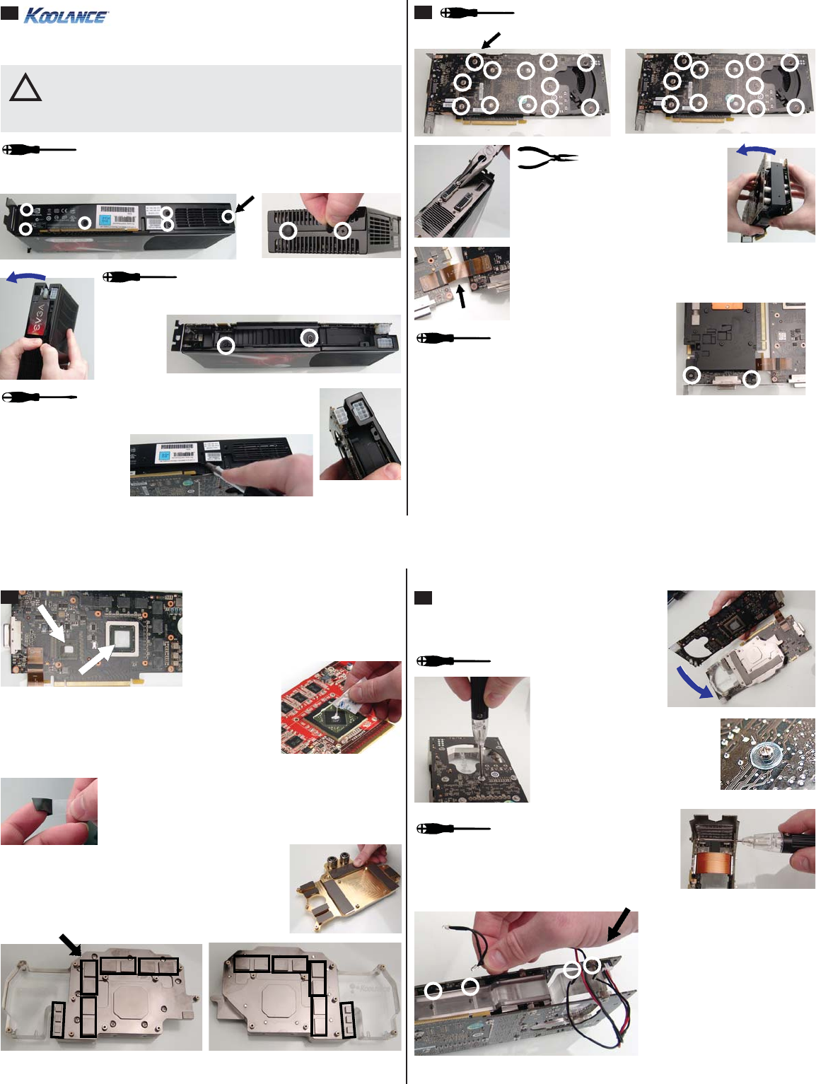
1
The initial screws holding the video card enclosure together
should be removed fi rst. There should be about 8 of these on
the bottom and rear ends of the video card.
Gently pry apart and remove the looser half
of the enclosure. This will give access to 2
more screws that require removal.
Removing the remaining half of the enclosure
is a little more complicated. It will be latched
near two points: the PCI-E slot board and the 8-pin power
plug. Gently pry the
enclosure over these
areas to remove it. Be
careful not to damage
either video board!
4
With thermal material in place, lay the
Koolance water block over the bottom video
board (the PCI-Express slot side).
Using the Koolance-supplied
screws and plastic insulating
washers, tighten all 12 screws on
the top video card. Then repeat
this for the bottom video board.
Replace the rear L-bracket and tighten all 4 DVI
port hex nuts. Using a small screw driver, replace
the two video board screws that threaded into the
L-bracket.
Koolance’s water block includes
a small strip of blue LED lights.
This can optionally be installed to
illuminate the water block.
For power, connect this LED strip
to the video card’s original fan
plug. Then slide each LED light
into the small receptacles in the
bottom of the acrylic water block
body. A small drop of hot glue can
help hold each LED in place.
2
Unscrew all four DVI
port hex nuts on the rear
L-bracket. Then gently pry apart the
loosened video board (no longer attached
to this L-bracket).
The heat sink and fan can now be carefully removed. Original thermal
paste may present additional resistance while removing the heat sink.
Unplug the heat sink fan wire. Remove the original memory and VReg thermal
pad material, and wipe any residual paste from the main GPU chipsets. Do this
for both video boards.
With the enclosure removed, the primary video board screws
can be accessed. Remove all 12 of these from each video
board (24 screws total).
Both data ribbons should remain connected to both video
boards. If either comes loose during diassembly, reconnect
the ribbon to the appropriate plug.
The fi nal two screws holding the L-bracket and
original heat sink can now be removed.
Thermal paste is required only on the two
main GPU’s, and the single PCI-E chip.
The other areas will utilize the included
heat transfer pads.
Two different sets of heat transfer pads are included. Each
set has a different thickness, and one should be chosen that
offers best contact with your video card. Thermal pads may
have plastic fi lm on one or both sides that must be removed
before application.
Place heat transfer pads to cover each additional area
cooled by the Koolance liquid block. This includes memory
rows and power/VReg areas on both video boards.
Thermal pads can be cut to accommodate different
shapes.
3
Spread thermal compound on the GPU thinly and evenly
using the included paste packet, or a piece of thick paper
(such as a business card). Thermal paste should not be
placed on the surrounding metal support frame or small
surface soldered components.
 (2 Seiten)
 Manymanuals.com
 Manymanuals.de
 Manymanuals.fr
 Manymanuals.it
 Manymanuals.pl
 Manymanuals.cz
 Manymanuals.es
 Manymanuals-pt.com
Kommentare zu diesen Handbüchern